Execution Tree
VisualFLOPER (as FLOPER) includes the possibility to draw the execution tree of a program. Click "Generate Partial Execution Tree..." button, or select Run > Generate Partial Execution Tree, and intro a goal in the dialog. VisualFLOPER will draw a partial execution tree for the program of the project and the given goal, as seen in Figure 1.
 - large.png)
Figure 1: Tree in VisualFLOPER
The root node is the first state of the execution (roughly speaking, the goal of the program). There is a sequence of yellow and blue nodes. Yellow nodes represent the states of the program during its execution (and includes a query to be solved and a set of substitution of variables), and blue nodes represent:
- A rule of the program: The rule used to achieved the transition between the previous state to the next state. Rule R0 represent AS3 steps.
- A kind of interpretive step: 'is' represents formal interpretive steps, 'sis' represents small interpretive steps (with 'sis1' and 'sis2' for the two kinds of small interpretive step), and 'result' omits the entire interpretive phase.
The user is able to select the kind of interpretive steps in the tree selecting Options > Change Interpretive Step Mode. The dialog that appears (see Figure 2) has three options:
- large: To omit the Interpretive Phase
- medium: Formal Interpretive steps.
- small: Small interpretive steps (this option generates a larger Interpretive phase in the tree because depicts more information of each step)
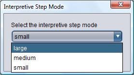
Figure 2: Option "ismode"
Compare the three differet modes in Figure 3.
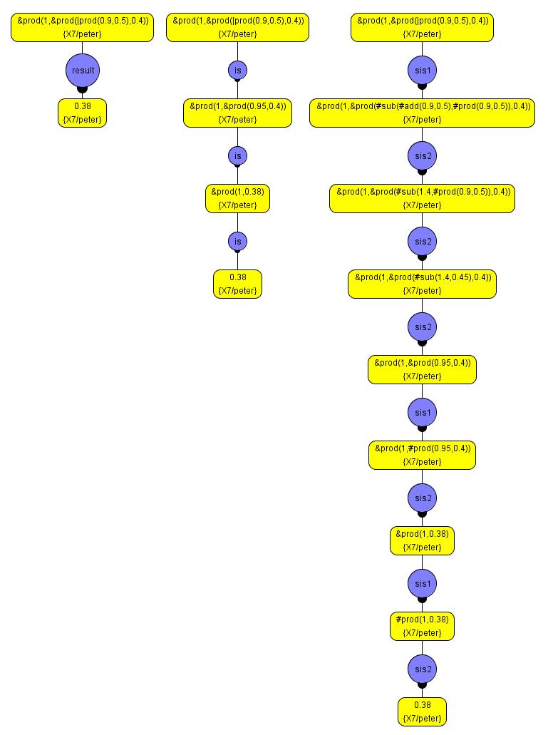
Figure 3: Comparison between the three kinds of interpretive steps
The resulting tree is a partial execution tree of the program with a finite number of steps, so not all leaves will be final states (solutions), but they may be pruned branches. To change the number of steps of the partial execution tree, select Options > Change Max Tree Depth, and write the new maximum in the dialog (see Figure 4).
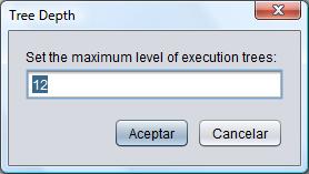
Figure 4: Depth dialog
This option can be used to execute fuzzy programs without the limitations of the Run option:
- No infinite loops: As the maximum depth of the tree is finite, it is not possible to fall into an infinite loop.
- AS3 steps performed: The fuzzy program is interpreted step by step by FLOPER itself, not by Prolog, so it can manage AS3 steps.
The disadvantages are that there might be solutions deeper in the tree, that are pruned, and the execution is less effitient (as it is interpreted by FLOPER, nt by Prolog).
The resulting partial execution tree can be saved as:
- PNG file.
- TXT file (using FLOPER notation)
- XML file.
VisualFLOPER can load trees from these three formats, too.
Leaves option is closely related with Tree option, but it returns only the leaves of the tree. Leaves option is focused on final results of the execution, while Tree option show all the computations.
In FLOPER, to obtain the execution tree of a program, intro the command 'tree'. The tree is given as text. Each row, containing a prefix and a state, represents a node of the State Transition System reached performing a rule related to the prefix (see Figure 5). The indent of a row represents its deepness in the tree. A node descends of the less indented previous node.
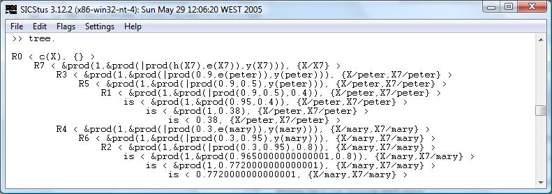
Figure 5: "tree" option as seen in FLOPER
The meaning of the prefix is the same as the blue nodes in VisualFLOPER.
To choose the interpretive step mode, use option ismode and write 's' for small interpretive step, 'm' for formal interpretive steps and 'l' for omiting the Interpretive Phase, as seen in Figure 6.
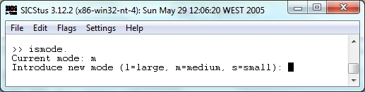
Figure 6: "ismode" option as seen in FLOPER
To choose the maximum depth of the tree, use option depth and write the corresponding number.
FLOPER includes the Leaves option (see Figure 7) explained above.
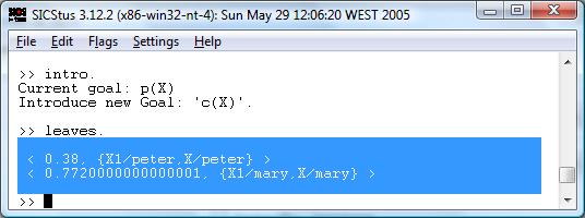
Figure 7: "Leaves" option as seen in FLOPER